


Descrizione
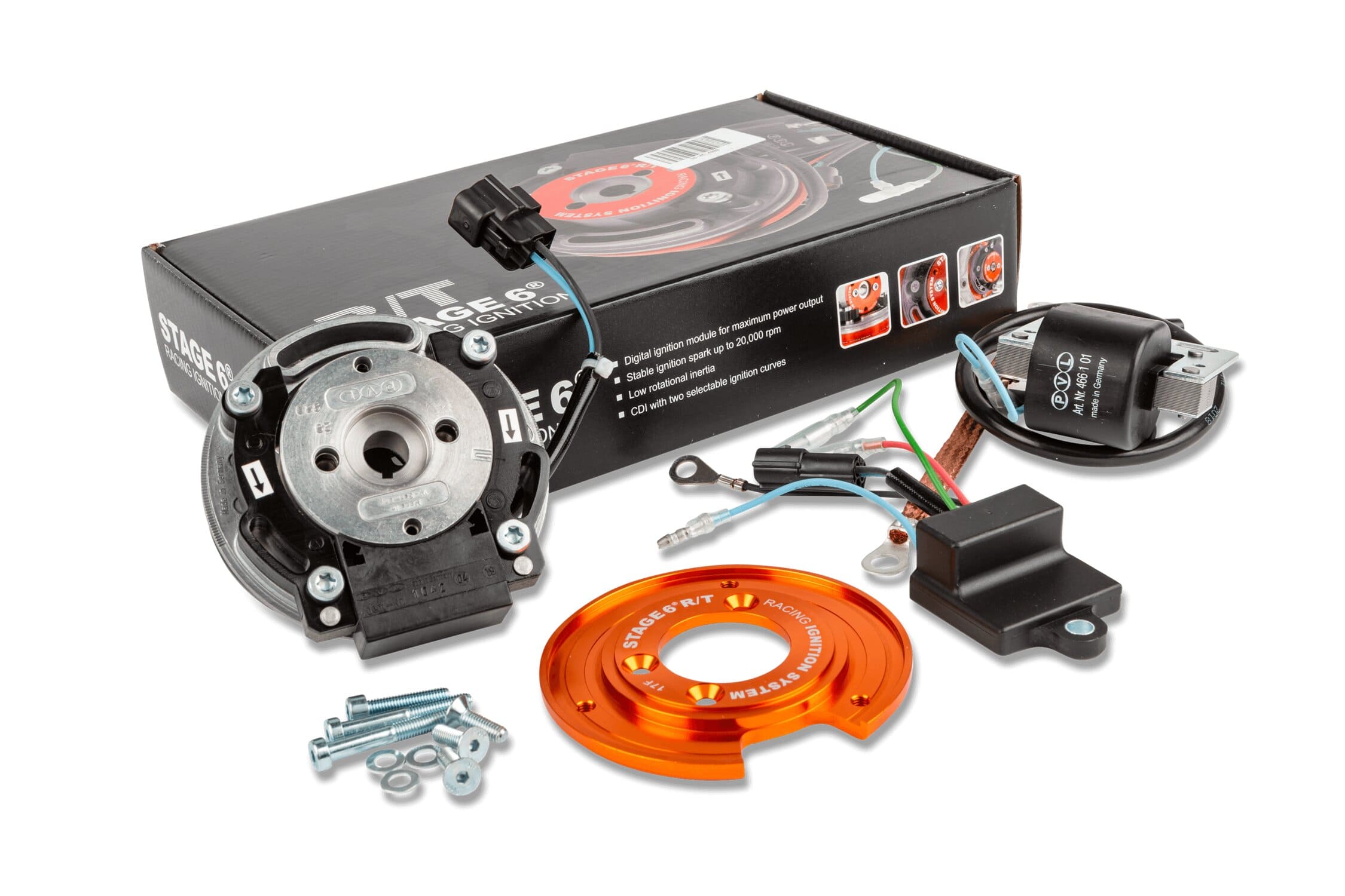
Cod: S6-4514000 Internal Rotor Ignition Stage6 R/T, Piaggio
STAGE6 R/T internal rotor ignition for air and liquid cooled Piaggio - Gilera engines.
In collaboration with PVL, the new STAGE6 R/T internal rotor ignition is born
- digital ignition system
- programmed ignition for effective advance synchronization even at 20,000 rpm
- two selective advance curves (via gear switch)
- internal rotor with low rotational inertia
- Engine shutdown function (via mass button)
ATTENTION: the kit does not include the ADDITIONAL WEIGHTING FLYWHEEL or the CURVE SELECTOR, which can be purchased separately
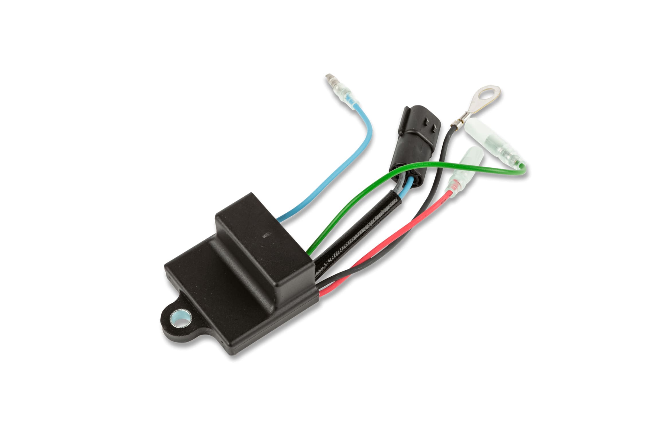
Control unit
- digital ignition with variable advance control unit
- small and light, thanks to SMD assembly technology
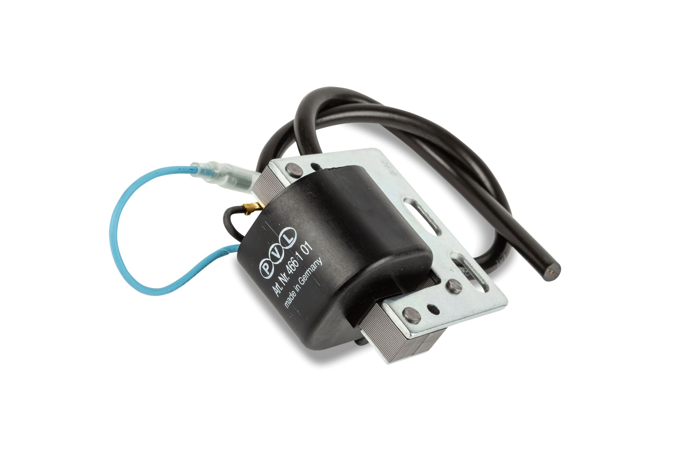
High voltage coil
- Start of ignition already at about 400 rpm
- Highly efficient capacitive discharge (CDI)
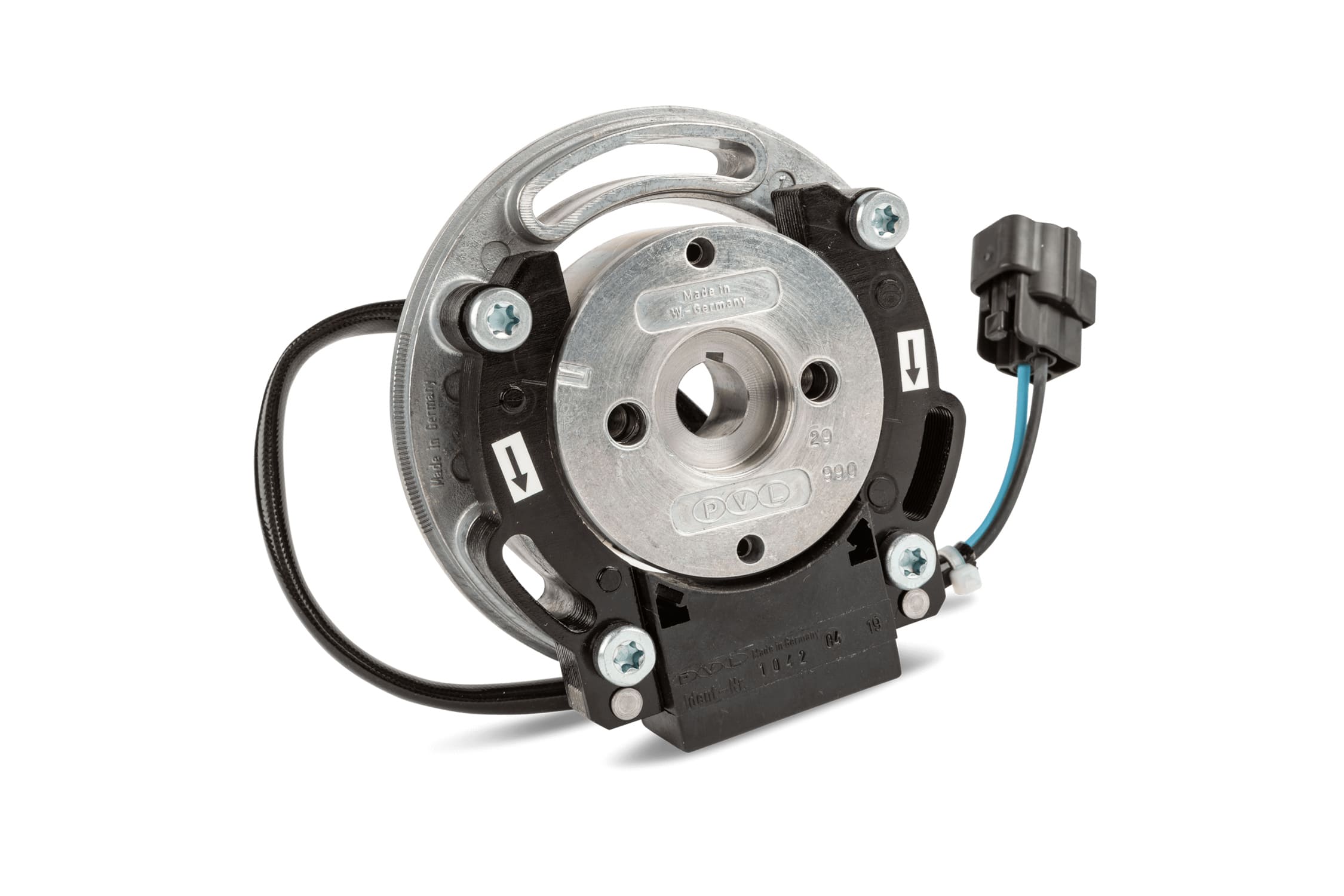
- constant discharge voltage Stator rotor unit:
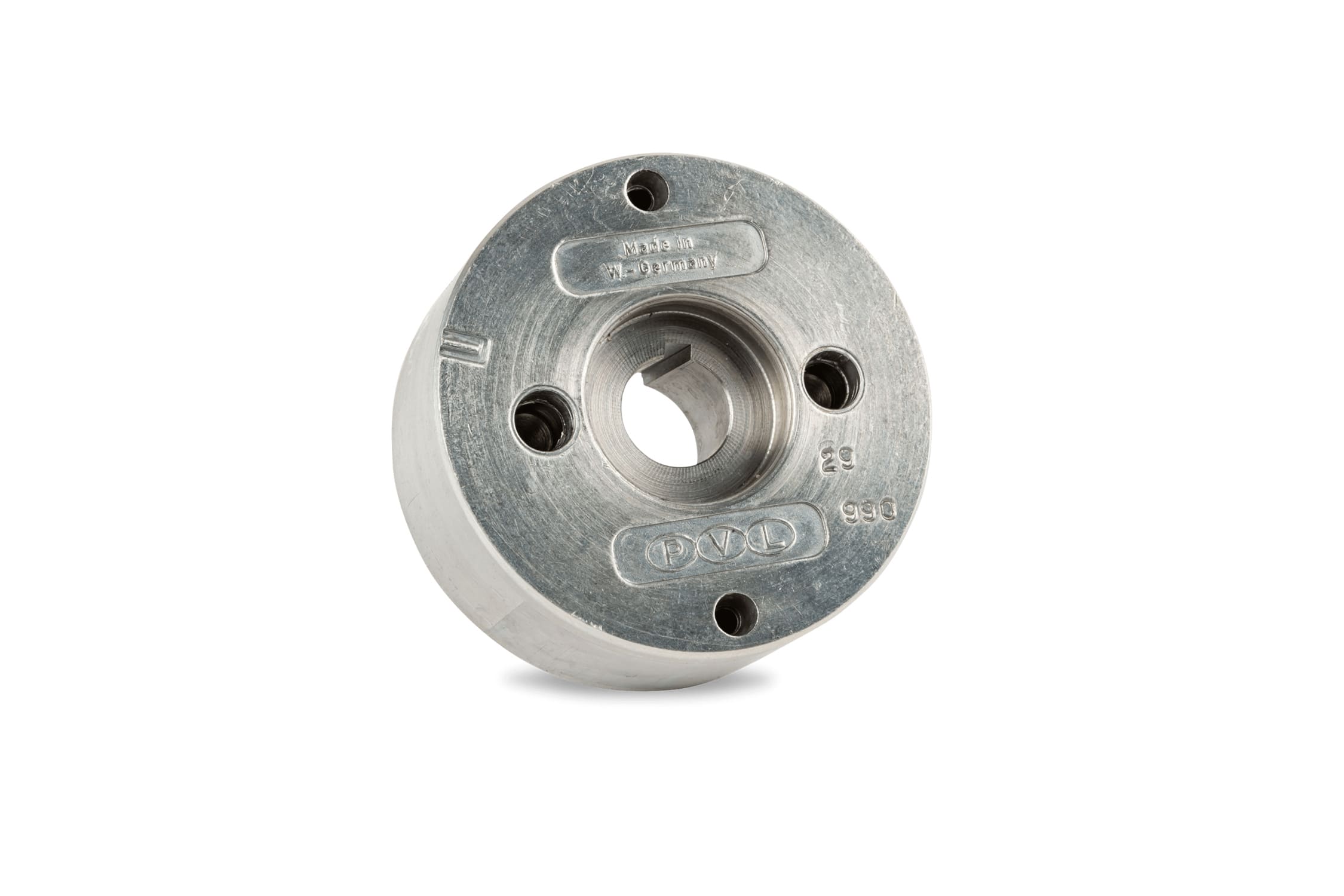
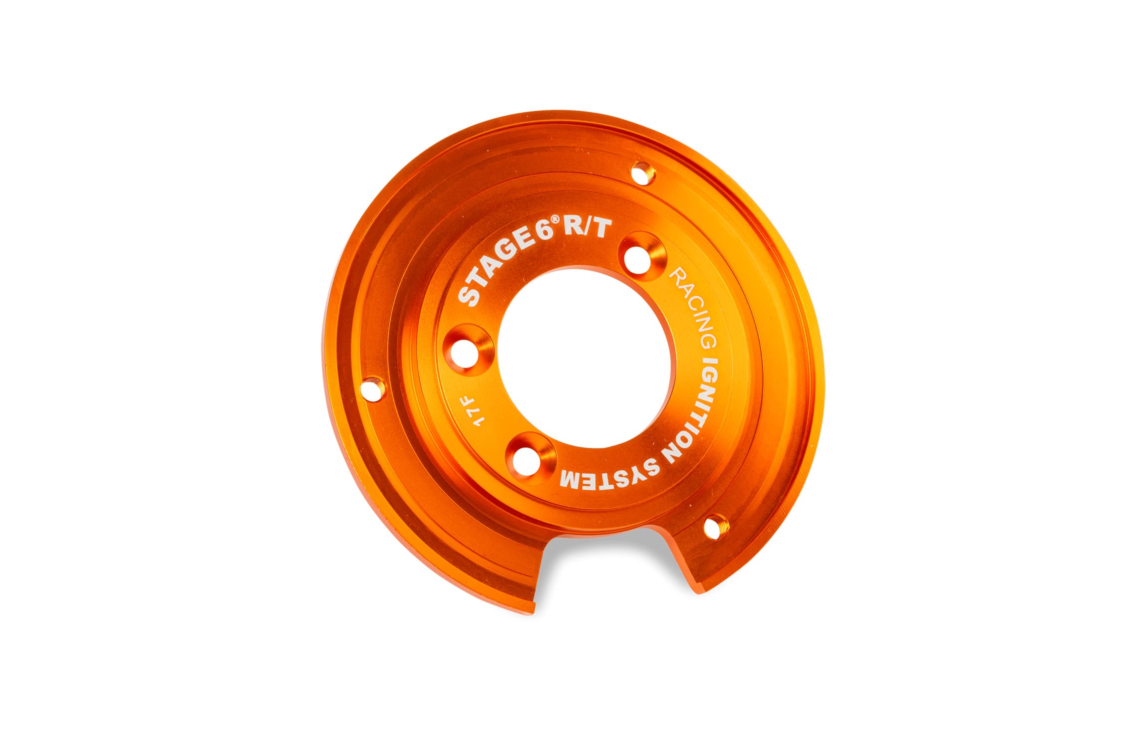
Rotor - stator group
- lightweight internal rotor
- low rotational inertia
WIRE CONNECTION FOR MAPPING SELECTION
To select the 2 advance curves, you will need to use a 2-contact switch to connect to the chassis ground.
For a perfect installation, we recommend LEONELLI GEAR SWITCH art. 034.E00. Installation is very simple: first connect the green wire coming out of the control unit to the gear switch; the gear switch has a wire with a ring faston, to be connected to ground on the frame.
- CURVE 1 : this curve is suitable for drag acceleration races; it can be selected by clicking on the MAP1 button on the LEONELLI gear switch. In this case, a connection of the green wire to the chassis ground is created
- CURVE 1 : this curve is suitable for track racing; it can be selected by clicking on the MAP2 button on the LEONELLI gear switch. In this case, the connection of the green wire to the frame ground is interrupted
The function of the gear switch is to connect the green wire to the frame ground: if the green wire is connected to ground, CURVE 1 is activated; if the connection is interrupted, CURVE 2 is activated. You can also use this function by using a simple 2-contact button.
CONNECTING WIRE FOR ENGINE SHUTDOWN
The STAGE6 ignition also allows you to turn off and interrupt the engine current. This function can be used by installing a RACING MASS SWITCH. A red wire comes out of the control unit, which must be connected to the mass switch. By removing the button from the vehicle, the red wire is connected to the chassis ground, which immediately turns off the engine.
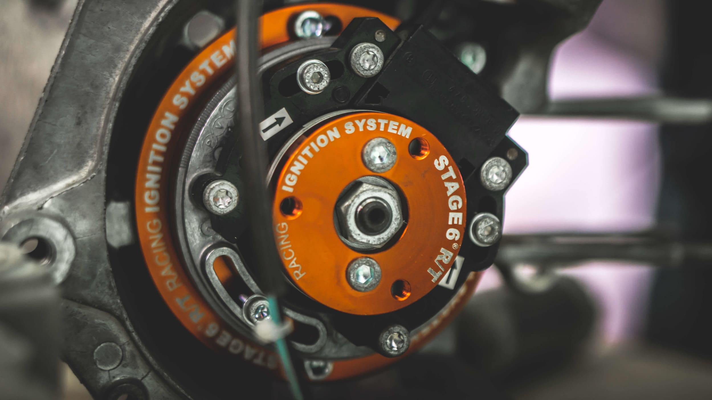
Mounting on Piaggio LC engine
The weight plate is not supplied, but can be ordered separately using code S6-4514002. Special equipment is required to install the ignition.
The assembly example focuses on a Piaggio 50cc LC engine. The original ignition has been removed from the engine. As a first step, we recommend checking the integrity of the package and its contents, as well as the presence of the necessary equipment. For the simple assembly of the ignition, you only need an M3 and M4 Allen key, at least an 18mm wrench or an 18mm socket with its ratchet. For locking the crankshaft, we recommend a specific tool that acts on the variator side, a piston lock or a pneumatic gun.
For correct ignition timing you need a micrometer, for an even more precise setting we recommend a comparator
The stator support flange is fixed using the 3 M4 screws supplied on the engine crankcase; the screws are fixed using threadlock. Now fit the stator, taking care to place the cable correctly in the appropriate space. Screw in the 3 Allen screws without locking the stator, to allow the timing to be carried out later by rotating it. The original key is also used on this ignition, avoiding movements of the rotor. Now insert the rotor onto the crankshaft, taking care to phase it with the key, then press it down fully. Fix the rotor with the appropriate M12 nut (lock the crankshaft using a specific tool that acts on the variator side, a piston lock or a pneumatic gun). Rotate the engine clockwise until reaching the top dead center and reset the comparator. Now rotate the crankshaft anticlockwise (1 turn of the comparator corresponds to 1mm). The dial indicator will rotate counterclockwise for three complete turns and 0.2 mm, until it reaches the value of 3.2 mm before the top dead center. Note how the reference lines imprinted on the stator and rotor are approaching each other. Keep the crankshaft absolutely still in this position (3.2 mm from the top dead center) and rotate the stator until the two reference lines match. Check the accuracy of the operation several times, finally tightening the stator fixing screws with the aid of threadlocker.
The coil must be fixed to the frame, making sure that the mounting area is unpainted and clean, to ensure good electrical contact. Painted and/or rusted frames near the mounting areas can cause malfunctions and breakages. Try to protect the EEPROM from liquids and vibrations. The black cable, as well as the coil, must have a clean and unpainted contact to the frame. The blue EEPROM cable must be connected to the blue coil cable. The red cable must be connected to the switch. Connecting the latter to ground interrupts the ignition and the engine switches off. If the green cable is brought to ground, the second advance curve (mapping) is activated. The map change must always and strictly be carried out with the engine off, to avoid damaging the EEPROM. Through an optional switch, this process can be facilitated, avoiding annoying connections and disconnections of cables.
Map #1: Green wire not connected to ground – recommended for drag racing
Mapping #2: Green wire connected to ground – recommended for track use
The connection between stator and EEPROM is generated by means of the appropriate plug.
The ground cable must be connected to a ground point on the frame and the engine crankcase, in order to create a bridge between the two.
In general, cables must always be routed in such a way as to avoid possible damage, especially during the movement of the vehicle (heat, rotating masses and engine case flexing). All screws must be secured strictly with appropriate threadlocker. For use in the Stage6 Racing Cup, the rotating elements (rotor) must be covered with a special cover.
For Minarelli engines, the assembly instructions differ in the following points:
· An M5 Allen key is required for assembly.
· The stator support flange must be fixed using 2 M5 x 22mm screws.
· The water pump drive plate must be fixed using 2 M5 x 30mm screws.
Advance variation based on the race:
· Stroke 39.2 - 39.3mm
Connecting rod 80mm 3.20mm
Connecting rod 85mm 3.17mm
Connecting rod 90mm 3.13mm
· Stroke 43.0mm
Connecting rod 80mm 3.57mm
Connecting rod 85mm 3.53mm
Connecting rod 90mm 3.49mm
· Stroke 44.0mm
Connecting rod 80mm 3.68mm
Connecting rod 85mm 3.63mm
Connecting rod 90mm 3.59mm
· Stroke 45.0mm
Connecting rod 80mm 3.78mm
Connecting rod 85mm 3.73mm
Connecting rod 90mm 3.69mm
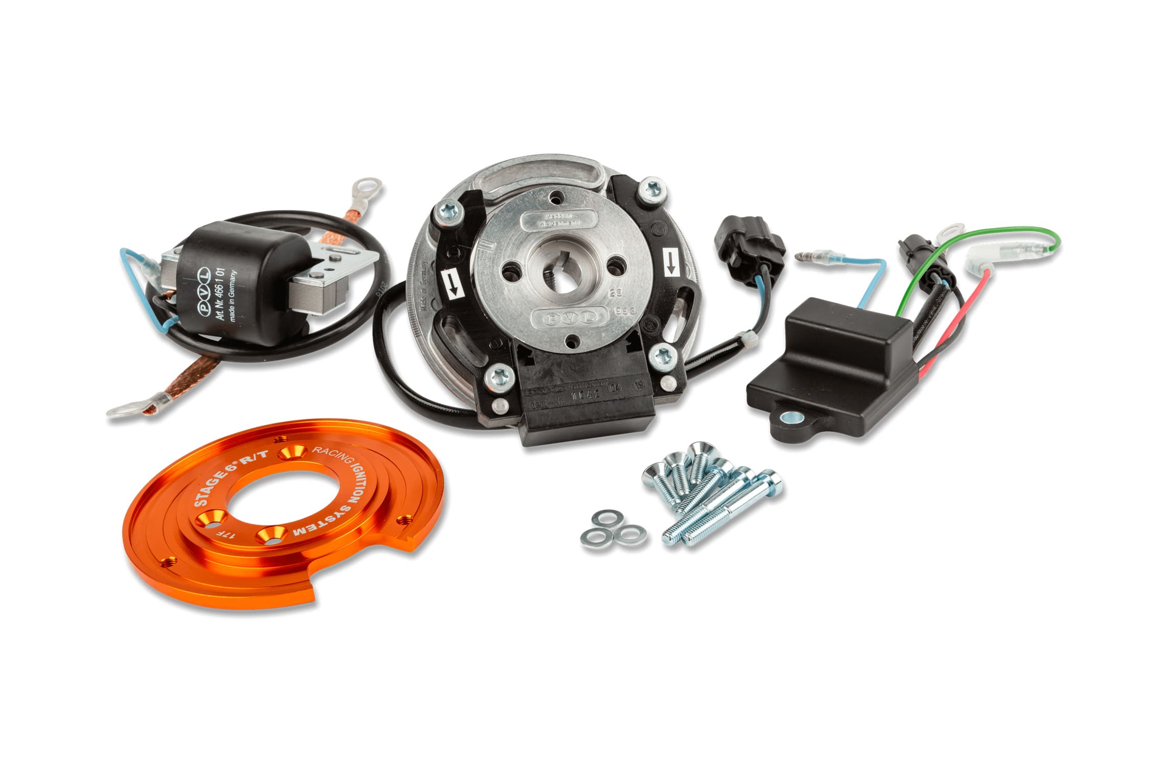
SPARE PARTS
- FIXING FLANGE
- IGNITION WEIGHING PLATE
- STAGE6 R/T STATOR
- IGNITION SCREW SET
- STAGE6 R/T DIGITAL CONTROL UNIT
- HIGH VOLTAGE COIL STAGE6
- STAGE6 R/T ROTOR
- IGNITION CONNECTOR SET
- GROUND CABLE
The Product may be reserved exclusively for competitions in places specially designated for such purposes according to the provisions of the competent sports authorities. We decline all responsibility for improper use.
FOR INFORMATION DO NOT HESITATE TO CONTACT US
Billaricambi staff
Per qualsiasi dubbio o informazione contatta lo staff Billaricambi SRLS.
Compatibilità del prodotto
| Marca | Modello |
|---|
Scheda tecnica
Scheda tecnica in aggiornamento. Le informazioni per questo prodotto saranno disponibili a breve.
Spedizione & resi
Metodi di spedizione
-
Italia
Spedizione gratuita: per ordini compresi e superiori a 370€ (corrieri BRT e SDA)
Spedizione standard: 8,00€ (corrieri BRT e SDA)
Spedizione standard isole: 9,20€ (corrieri BRT e SDA)
Spedizione con contrassegno: + 4,90€ (corrieri BRT e SDA)
Tempi di consegna: 24–48 ore. -
Europa
Spedizione standard: 27,90€ (corriere DHL)
Tempi di consegna: 3–5 giorni. -
America
Spedizione standard: 48,90€ (corriere DHL)
Tempi di consegna: 5–7 giorni.
Puoi aggiungere la spedizione assicurata per proteggere il tuo ordine da furti, smarrimenti o danneggiamenti durante il trasporto.
Resi e diritto di recesso
- Il consumatore ha diritto di recesso entro 14 giorni dalla consegna, senza penalità e senza doverne specificare il motivo (D.Lgs. 206/2005).
- Le spese di restituzione sono a carico del cliente e la merce deve essere restituita in perfetto stato di conservazione, inutilizzata, integra, con sigilli, etichette e imballi originali.
- Il rimborso viene effettuato sullo stesso metodo di pagamento entro i termini di legge, dopo la ricezione e la verifica della merce resa.
- Il diritto di recesso non si applica agli acquisti effettuati con Partita IVA.
In caso di prodotto difettoso o di errore da parte nostra, ci occupiamo noi della sostituzione o del rimborso, includendo le spese di spedizione e di reso ove previsto. Per tutti i dettagli completi consulta la nostra Politica di reso e rimborso .
Guida all'installazione di S6-4514000 Stage6 R/T Internal Rotor Ignition, Piaggio - Gilera
Procedura consigliata per montaggio e controlli finali (prima di avviare il motore).
-
STEP 1Prepara il vano motore, assicurandoti che il veicolo sia spento, stabile e posizionato su un supporto sicuro. Rimuovi l’accensione originale conforme alle istruzioni del costruttore.
-
STEP 2Verifica l’integrità del kit Stage6 R/T e assicurati di avere a disposizione gli attrezzi necessari, quali chiavi a brugola M3 e M4, chiave inglese o bussola da 18 mm con cricchetto, e eventualmente attrezzi specifici per bloccare l’albero motore lato variatore (bloccasterzo o pistola pneumatica).
-
STEP 3Fissare la flangia di supporto statore sul carter motore utilizzando le 3 viti M4 in dotazione; applica frenafiletti sulle filettature per garantire una tenuta ottimale.
-
STEP 4Posiziona lo statore nella flangia di supporto, facendo attenzione a sistemare correttamente il cavo negli appositi alloggiamenti per evitare movimenti o danneggiamenti. Lascia le viti leggermente allentate per permettere la regolazione in fase successiva.
-
STEP 5Monta il rotore sull’albero motore facendo coincidere la chiavetta originale per evitare rotazioni indesiderate. Premi il rotore fino a completo inserimento.
-
STEP 6Avvita e fissa il dado M12 del rotore serrandolo con l’attrezzo specifico per bloccare l’albero motore lato variatore; regola il serraggio seguendo le specifiche del costruttore.
-
STEP 7Porta il motore al Punto Morto Superiore (PMS) e azzera il comparatore micrometrico posizionato sul pistone per la fase di accensione.
-
STEP 8Ruota l’albero motore in senso antiorario fino a raggiungere il valore di anticipo consigliato (ad esempio 3,2 mm prima del PMS per una corsa standard), mantenendo saldo l’alberino.
-
STEP 9Ruota lo statore fino a far combaciare le linee di riferimento impresse sullo statore e sul rotore. Blocca definitivamente le viti dello statore serrandole con frenafiletti.
-
STEP 10Fissa la bobina alta tensione al telaio in una zona pulita e sverniciata per garantire un buon contatto elettrico, evitando aree verniciate o arrugginite.
-
STEP 11Collega i cavi secondo lo schema:
- Nero a massa telaio
- Blu bobina al cavo blu EEPROM
- Rosso al comando di spegnimento (staccamassa), da collegare a massa per spegnere il motore
- Verde al selettore curve anticipo (interruttore a 2 contatti) per attivare una delle due mappature. -
STEP 12Installa un interruttore di cambio mappa in un punto comodo sul veicolo, collegando il filo verde all’interruttore e da questo alla massa del telaio; con filo verde a massa si attiva la curva 2 (uso pista), senza collegamento la curva 1 (accelerazioni drag).
-
STEP 13Verifica il corretto fissaggio di tutte le viti e il passaggio dei cavi, evitando che possano subire abrasioni o eccessive flessioni. Assicurati che il rotore sia protetto da un coperchio adeguato in caso di utilizzo in competizioni.
-
STEP 14Effettua un test di accensione a motore spento per controllare il funzionamento dell’interruttore di spegnimento e il cambio mappa tramite l’interruttore installato.
-
STEP 15Avvia il motore e verifica che l’accensione funzioni correttamente in entrambe le curve di anticipo, effettuando le prove su strada o pista secondo le condizioni di utilizzo. Regola ulteriormente l’anticipo se necessario, seguendo sempre le indicazioni tecniche specifiche del motore.